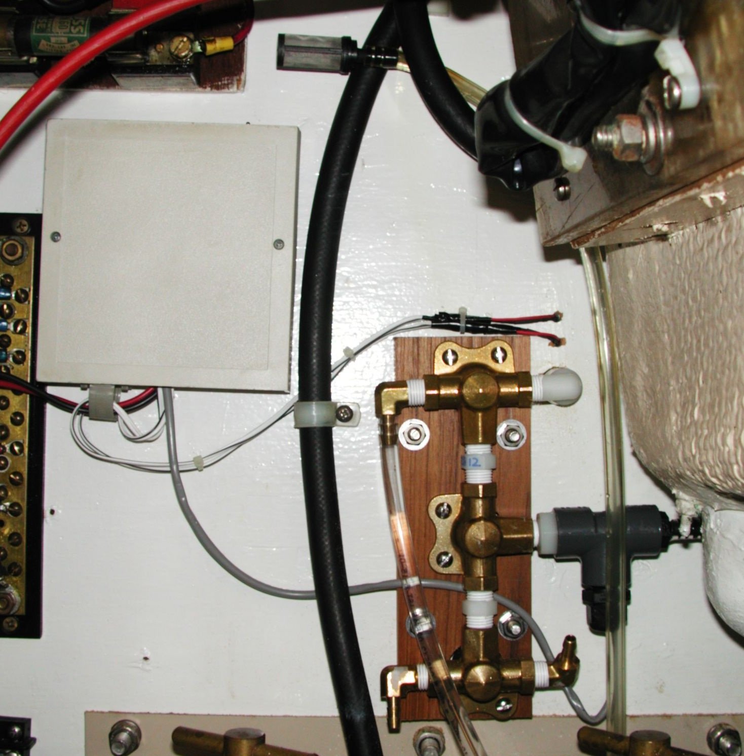
The watermaker output manifold The watermaker output manifold installation, as seen from the engine room. The water comes in to the T-fitting on the right, past the salinity detector; the upper outputs are to the bilge and test spigot; the lower outputs will be connected to the forward and aft water tanks. The salinity monitor electronics are in the box on the upper-left; the power and salinity LEDs poke through from the quarter-berth on the upper-right. The clear tube coming up to a little strainer at the top is the alternate watermaker input, for cleaning. The black hose coming down the middle is the fuel line; the filters are below.
5 Jan, 2002 18:23
By Ian Cameron Smith
Camera: NIKON E990